- Flex PCB Blog
- PCB Assembly Blog
- FPC Research Blog
- Preparation of FPC based on ultrasonic spraying method_4_Experimental Results
- Preparation of FPC based on ultrasonic spraying method_3_Experimental Procedure
- Preparation of FPC based on ultrasonic spraying method_2_Experimental Platform and Principle
- Preparation of FPC based on ultrasonic spraying method_1_abstract
- Research on Layout Design Method of Ultra-thin FPC_4_Analysis of Layout Design Methods
- Research on Layout Design Method of Ultra-thin FPC_3_Analysis of Layout Design Methods
- Research on Layout Design Method of Ultra-thin FPC_2_Analysis of Layout Design Methods
- Research on Layout Design Method of Ultra-thin FPC_1_introduction
- Research progress on polyimide FPC_2_the field of FPC
- Research progress on polyimide FPC_1_Introduction
- Analysis of Vibration Characteristics of FPCBs _4_Summary
- Analysis of Vibration Characteristics of FPCBs _3_Finite Element Analysis
- Analysis of Vibration Characteristics of FPCBs _2_Theory of Vibration Analysis
- Analysis of Vibration Characteristics of FPCBs Under Random Vibration_1_Introduction
- Design Methods for FPCBs_5_Practical Application
- Design Methods for FPCBs_4_Electrical Circuit Design and Examples
- Design Methods for FPCBs_3_Structure Design Method and Examples
- Design Methods for FPCBs_2_Component Selection Methodology and Examples.
- Research on Design Methods for FPCBs
- Application of MPW technique for FPCBs _4_Summary
- Application of MPW technique for FPCBs_3_Experimental results
- Application of MPW technique for FPCBs_2_Experimental setup
- Application of MPW technique for FPCBs_1_Principle of MPW
- Application of FPCB in PC motherboards_4_ Results and discussion
- Application of FPCB in PC motherboards_3_ Numerical analysis
- Application of FPCB in PC_2_ Experimentation
- Application of FPCB in PC motherboards
- A Bus Planning Algorithm for FPC Design _4_Experimental result
- A Bus Planning Algorithm for FPC Design _3_Proposed Algorithm
- A Bus Planning Algorithm for FPC Design _2_Preliminaries
- A Bus Planning Algorithm for FPC Design _1_Introduction
Application of magnetic pulse welding technique
for flexible printed circuit boards (FPCB) lap joints_1_ Principle of MPW
Modern electronic devices are required to be thin, lightweight and functionally sophisticated. Therefore, joining thin flexible printed circuit board (FPCB) in different shapes is receiving attention. FPCB and flexible cables constructed from polyester or polyimide film and such films are lightweight, flexible and thin. Varying circuit shapes, dimensions, circuit arrangements and different length cable arrangements may be constructed using FPCB. However, a disadvantage to the use of FPCB is the bonding problems. Yoonet al.(2007) studied bonding characteristics of FPCB using solder method and reported high electrical and mechanical properties, while the excessive growth of intermetallic compounds at the joint interface significantly degrades the performance and reliability of the solder joint. Maruoet al.(2004)investigated adhesive-bonding methods using anisotropic conductive adhesive or non-conductive adhesive for FPCB bonding but experimental results show poor electrical property and low mechanical reliability in joint interfaces. Unfortunately, the conventional boding meth- ods for FPCB do not appear to provide an economical and reliable solution to interconnection and construction challenges. The mag- netic pulse welding (MPW) provides an excellent and high speed method for achieving FPCB lap-joint. MPW uses magnetic pres- sure to drive the primary metal against the target metal sweeping away surface contaminants while forcing intimate metal-to-metal contact, thereby producing a solid-state weld. Several technical
research papers has been reported about MPW for exampleTamaki andKojima (1988) and Shribman et al. (2002)used conventional MPW method with solenoidal coil for joining tubular parts and investigated its feature. MPW has been theorized and tested for several decades, but equipment limits the total energy stored and this keeps weld lengths to the order of meters or less. Recently, MPW application rapidly growing in industrial application and new development make MPW method well suited for manufacture and assembly in wide range of application. Shribman andGafri (2001) introduced MPW technique for tube to tube applications. They studied the fundamental equations ofMPW process and illustrated some examples of similar and dissimilar weld applications with some interface microstructures. Uhlmann et al. (2005) also studied the applicability and the potentials ofMPW for joining of aluminum and magnesium structure which is a new solutions for modern lightweight structures applications. Daehn and Lippold (2009) also proposed a new MPW device and developed it for similar or dissimi lar thin sheet metal joints application. Recently, several works also were carried out on application of MPW technique in electronics micro-devices. For example, Kashani et al. (2008, 2009) developed a new low energy MPW system which can be used for bonding of wire to terminal plate in electronic devices or making small Copper and Manganin alloys joint as a shunt resistor for using at control circuits. The goal of this work was to introduce new low energy system with modified coil structure for using MPW technique in FPCB lap-joints application which has not been reported before. The present paper examines the detail of the welding process and welds quality characteristics for FPCB lap-joints in two cases: (1) with aluminum driver sheet and (2) without aluminum driver sheet.
2. Principle of MPW
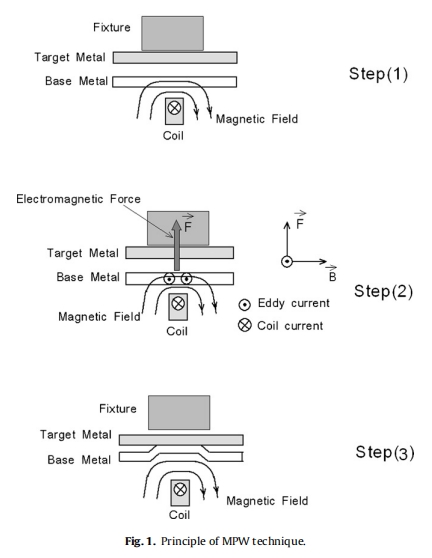
Magnetic pulse welding (MPW) uses electromagnetic force to accelerate one metal piece (base metal) against another stationary metal piece (target sheet). When a high magnetic field ![]() is suddenly
is suddenly
generated and penetrated into metal sheets, then the eddy currents (current density ![]() ) pass through them and as a result, an electro magnetic force of
) pass through them and as a result, an electro magnetic force of ![]() acts mainly on the base metal sheet and
acts mainly on the base metal sheet and
it is accelerated away from the coil and collides rapidly with the target metal sheet. The eddy current ![]() and the magnetic pressure p are given as following:
and the magnetic pressure p are given as following:
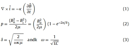
Where k, μ, τ, Bo and Bi are the electrical conductivity, magnetic permeability, thickness, the magnetic flux density at lower and upper surfaces of Al sheet, respectively. The depth of skin effect (ı) can be obtained by calculation of angular frequency (ω ) and it is governed by the complete MPW system’s inductivity L and its capacity C. The skin depth becomes important parameter specially for thin sheet metal bonding process. When the thickness of the base sheet metal is the same as the skin depth, then magnetic pres- sure equals 86% of its maximum value and it reaches 98% when the base metal thickness is twice of the skin depth. The appropriate skin depth and higher magnetic pressure can be adjusted by the frequency of the discharge current.
At the moment of collision the colliding surfaces can be cleaned by a large kinetic energy getting before the collision. The velocities attained during this process range from 200 m/s to 500 m/s and the joining process completed within microsecond. Because of the short impact period, the extent of heating might be minimal along the joints. Therefore, comparing to the traditional fusion welding process, no significantheat affected zones is produced in MPW joints and it can be noticed as a main advantage (Aizawa and Yoshizawa, 2001;Aizawa and Kashani, 2004).
Kakizaki et al. (2010) found that the surface oxide of the metal interfaces is disrupted due to the jet action and metallurgical bond- ing is achieved between clean surfaces. As shown in Fig. 1, the principle of MPW technique can be summarized into three steps: (1) producing high magnetic field, (2) acceleration of base metal, and (3) impaction and bonding.
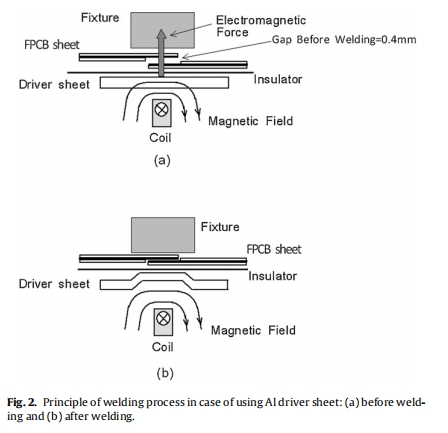
In the present experiment which has been carried out for FPBC lap-joints application, the base and target metals are thin and light and the skin depth is comparable with thickness of the FPBC copper layer. Therefore, the impactionis weaker in comparing with thick metal welding case. In this case, using Al driver sheet can increase the electromagnetic force and magnetic pressure. The impaction of Aluminum driver sheet with FPCB layers can make a solid state bonding between FPCB sheets. Fig. 2 shows the principle of welding process with using the Al driver sheet. The result of second experiment without using Al driver sheet also is reported in this paper for better comparison.